As usual, don't take our claims lying down! Come and see us at ExpoNG, Swanley October 31st and discuss them with us!
At several times in its development, the Péchot system was
influenced by British engineers.
This was certainly true in the 1880s. I believe that there is a connection
between the Handyside family of locomotives and the Péchot system.
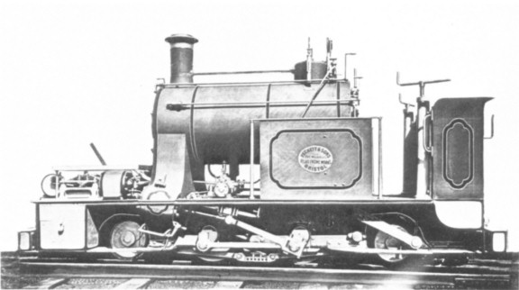 |
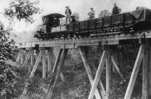
| From the collection of KP Plant. Courtesy of the Industrial Railway Society |
This is one of the six Fox, Walker
‘Handyside’ Locomotives 399 to 404 of 1878. The works photo has been doctored so
that the works-plate reads ‘Peckett.’
The story so far … In France the young Péchot, burning to
avoid any repeat of his country’s humiliation in the Franco-Prussian War, had
developed a portable 60 cm gauge railway which could bring French guns and,
more importantly, large quantities of ammunition within range of German forts. In
1882, after some years of theoretical work and experimentation at the
Decauville factory, Péchot sent a description in a bold Memorandum to the French Minister of
Defence/Ministre de la Guerre.
Unfortunately for Péchot, there was a rival system which had
been proposed by the Génie/Military Engineers…
In Britain,
there was also interest in railways for military support. Since the early
1870s, an 18” (45cm) gauge railway had existed at the Chatham Dockyards, Kent.
A gauge so narrow was chosen because it could tolerate tight bends. It was therefore
cheap to engineer - and convenient for running inside buildings. In the early 1880s, the young
Péchot had considered the metric equivalent but after careful theorising and experimentation
decided that 60cm gauge could offer almost the same advantages with fewer
drawbacks.
 |
| Courtesy of the Industrial Railway Society |
This picture of the Handyside gripper originally appeared in 'Iron' magazine 1874.
Mr Henry Handyside, formerly Assistant Engineer to the
Governor of Nelson Province New Zealand, made a most interesting attempt to fit 18”
gauge to the demands and problems of railway gradients. He invented a
steep gradient gripping strut capable of holding a locomotive and a train. The
theory was that the grippers would keep the locomotive in pace while it acted
as a stationary engine with winch. Manageable sections wof the train could be pulled up (or down). Supporting subscribers of the Handyside Steep Gradient Company included E. Fox, F.W. Fox and E. Walker. Fox, Walker & Co of the Atlas Works near Bristol funded much of the development of his system.
Drawings appeared in Iron Magazine 17th October 1874 showing
a proposed conversion of a Manning Wardle to take the winding engine to be used in conjunction with the Handyside Gripper.
 |
| Courtesy of the Industrial Railway Society/Roger West |
The proposed conversion of Manning Wardle no 448 0-4-0 ‘Burgoyne.' The drawings by Roger West are a clarified version of the
originals which appeared in the magazine. The winding engine is of the ‘non-reversing, no-lead’ type typical
of the period.
Just as with their Continental equivalents, the Royal
Engineers took some convincing. Equally, as with Péchot and his commercial backer Paul Decauville, Handyside had support from Fox, Walker and Co. The Handyside System
was tested using standard gauge in 1875. This finally persuaded the Royal
Engineers to have a look. On 12th
September 1876, an 0-6-0 ST locomotive equipped with the gripping strut was to be put through its paces in front of Major Percy
Smith RE and Captain Sale RE at a 1:14 gradient section of the Hopton Incline,
Crompton and High Peak Line, Derbyshire. The Royal Engineers reported that the
system had problems but potential.
In November that year, the RE proposed to use the Handyside
system for 18” gauge. They wanted to link Chatham
with Fort Borstall, at the time under construction, and ordered six special locomotives. David Smithers remarks that the design was ‘influenced by the double Fairlie principle ( in his 18” Gauge Steam
Railways OPC 1993 p109.)’ In 1878, the Atlas Works of Fox, Walker & Co duly supplied six locomotive (Works Nos. 399 to 404) which were fitted with the
Handyside Steep Gradient Apparatus.
By May 1879, the RE were ready to report on the performance
of the new system. The trial railway in Chatham
consisted of three bridges, four turnouts, several tight bends and some
gradients, up to 1 in 11. The railway
was ‘as standard’ for a ‘trench railway’ according to the Minute of the RE
Committee 2nd May 1879. The locomotive was able to pull 10 tons
(Imperial) up a I in 10 incline. A number of problems emerged, the chief one
being that trains could not cope with poorly laid track.
In 1881, and again in 1883, one locomotive at least was
partly overhauled to try to meet the challenges. A report from Major Hogg fell
on the desks of the senior RE Committee and appeared in the RE Journal for
September 1885. It was unfavourable. In Hogg’s opinion, 18” gauge
locomotive-worked railways were not suitable for siege train purposes on the
grounds of cost and safety.
It should be noted that in the late 1870s, the British Army
were more inclined to put money and effort into developing military railways.
They feared a new war in Russia.
By 1881, the threat had receded and the impetus was lost. The Committee
therefore decided to shelve the siege train project; a metre gauge system would
answer their purposes better. No more was done. In due course, the official
siege train gauge was changed to 2’6” though by 1914, this consisted of a mere 2 ½
miles of track.
I must declare an interest here. In 1895, ten years after
these events, my great grand-father, then Major Louis Jackson, was Chief
Instructor of Fortifications and Engineering at Chatham.
 |
| Louis Charles Jackson later Sir General Louis Charles Jackson 1856 to 1946 |
In the period 1882 to 1885, events in France followed a similar pattern to Britain.
The Péchot Memorandum of 1882 was accompanied by some
illustrations.
 |
| Illustration from the Péchot Memorandum of 1882 Courtesy of Raymond PÉCHOT |
Here the locomotive pulling a large gun is being winched up a gradient. Though Péchot gives many details for
other parts of his system, he does not, apart from a brief reference in
Appendix 8 of his Memorandum, expand much on winch haulage systems. Why not? Everything else in the Memorandum is meticulously explained. It is hard to believe that he was
not following the RE and Atlas works trials in England.
 |
| From an advertisement 1875 Courtesy of the Industrial Railway Society |
The advertisement dated 1875 for the Handyside Steep Gradient Company shows
gripping struts on the second wheel of a Fox, Walker Atlas Works 0-6-0. A short
test-track was constructed at the Atlas works, Bristol – this engraving was based on fact! A
hauling drum for pulling loco and train up the gradient was also used at the
trials. The two systems bear direct comparison.
An enthusiastic officer, in the French case Péchot, with the
backing of a private company, in this case Decauville, tried to solve the
Army’s transport problem in covering the last ten miles between an existing
railway station and a fort. Trials were performed from July 1883 to June 1885,
basically at the expense of Decauville and existing civilian railways.
The French Génie/Engineers discovered the interesting fact that an pre-existing
metre gauge railway was the most cost-effective way to move supplies. Péchot
was reprimanded for suggesting otherwise. Just as in Britain, the senior engineers
reported that the way to move supplies in war-time was to requisition metre
gauge stock and left it at that. In my book Colonel Péchot: Tracks To The
Trenches, I expand on this decision with many exclamation marks!
 |
| Courtesy Tim Dowling: Decauville locomotive similar to the one in the Péchot drawing. It is pictured on the Phu Lang Thuong-Lang
Son, Annam/modern Vietnam. A 60cm gauge railway was built in 1889. This was replaced, starting in 1896 with a
metre gauge railway |
In France, the Péchot system was mothballed then revived. This was partly because of the remarkable character of Prosper Péchot, partly due to politics. Unlike for the British Isles, the
chief enemy of France was Germany, just
over the frontier. To keep her away a network of fortifications stretched along
eastern France. In 1886, these forts were threatened with a deadly new threat,
artillery using new high explosives. It became essential to protect them. Each fort was therefore surrounded in turn with other forts! A handy, budget line of communication was
needed and Péchot’s ideas were revisited. Perhaps if the free Press had not
become involved or if the Minister of Defence had not been a comparative
outsider, immune to the in-fighting between the Génie and Artillerie, the
problem would have been quietly buried.
As it was, in 1888, the système
Péchot was declared the official railway linking all the frontier forts. By
the early 1890s, a 60cm network of nearly 700 km/450 miles was in construction,
to be operated by 56 Péchot-Bourdon locomotives. These owe something to 5 tonne
Decauville locomotive design but were, in Péchot’s own words ‘in the spirit of
Fairlie’.
It is no coincidence, I have argued in the Péchot biography, that the
Germans suddenly switched to 60cm gauge for military applications and had over
1000 km of their Feldbahn system available in 1914.


